 Up
Up
|
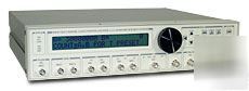
SR400 Dual Channel Gated Photon Counter * Two independent counting channels * 5 ns pulse-pair resolution * Gated and continuous modes * Gate scanning for time-resolved counting * Gate and discriminator outputs * GPIB and RS-232 interfaces The SR400 Dual-Channel Gated Photon Counter offers a convenient, integrated approach to photon counting that avoids the complexity and expense of older counting systems. No longer is it necessary to mix and match amplifiers, discriminators, gate generators and counters. The SR400 combines all these modules into a single, integrated, microprocessor controlled instrument. Complex measurement tasks such as background subtraction, synchronous detection, source compensation and pile-up correction can all be performed easily with the SR400. The SR400 has two independent channels that can count at rates up to 200 MHz. Different counting modes allow you to count for a fixed amount of time, until a certain number of counts have been received, or for a fixed number of triggers. Each counting channel has its own gate generator providing counting gates as short as 5 ns or as long as 1 s. The gates can be set in a fixed position relative to the trigger signal, or scanned to measure lifetimes or recover time-varying waveforms. The actual inputs to the counters can be viewed as NIM level pulses from the discriminator outputs on the front panel. The discriminated pulses are negative going from 0 to -0.7 V. The DISC outputs are very useful when adjusting discriminator thresholds or gate timing. Signal Inputs and Discriminators Both analog signal inputs (A and B) are internally terminated into 50 ?. The inputs accept signals between ±300 mV and are protected to ±5 VDC. Each input is followed by a DC to 300 MHz amplifier, allowing detection of pulses as small as 10 mV. If additional sensitivity is required, a remote preamplifier (like the SR445) can be used. Discriminators are provided for each channel with a selectable threshold from -300 mV to +300 mV in 0.2 mV steps. Pulse-pair resolution is 5 ns, and pulses of either polarity may be detected. Each threshold may be programmed to scan in either direction with selectable step size. This can provide a pulse height analysis (PHA) output and is useful for choosing photomultiplier tube bias or discriminator levels. The SR400 may be programmed to cycle from 1 to 2000 count periods in a single scan. At the end of the programmed scan, the counters may be stopped or the scan may be restarted. Consecutive count periods are separated by a "Dwell Time" which can be set from 2 ms to 60 s. During the Dwell Time, counting is disabled and data may be transferred or external parameters may be changed. The dwell output provides a TTL signal which is high during the dwell time. This can be convenient for interfacing other instruments used in the experiment. The front panel can display counts up to 109. Results from both counters can be displayed individually or combined as A-B or A+B. A front-panel D/A output provides an analog signal proportional to A, B, A-B, or A+B, depending on the counting mode. The scale may be logarithmic (1V/decade) or linear. Built-in RS-232 and GPIB interfaces provide a convenient means of controlling the instrument and retrieving data. While the SR400 is scanning, each of the count values for the A and B counters are stored in a 2000 point internal buffer. This buffer can be transferred on a point-by-point basis, or dumped all at once through either interface. Counters A, B, and T have independent discriminators when counting the signal inputs. All discriminator levels may be set to a fixed level or scanned. Both the A and B gates may be fixed in time or scanned. The gate outputs show the positions of the gates with respect to the discriminator outputs. The number of count periods or data points in a scan may be set from 1 to 2000. The duration of one count period is determined by the preset condition. The time between consecutive count periods is the dwell time and can be set from 2 ms to 60 s. The dwell output will be TTL high during the dwell time. This output can be used to trigger external devices. At the end of a scan (of 1 to 2000 count periods), counting may be programmed to stop or start the scan over again. The start key begins the first count period of the programmed scan. The stop key terminates the current count period and pauses the scan. If scanning, gates and disc levels are held at their current values. Pressing the stop key while in a paused condition will reset the scan, and all scanned parameters will return to their start values. Pressing the start key while paused resumes the scan by starting the next count period. The dwell time may also be set to external. In this mode, count periods begin with the start key or external start input (TTL rising edge). Count periods terminate with the preset condition, the stop key, or the external stop input (TTL rising edge). Pressing the stop key while not counting resets the scan. All count data is internally buffered for one scan. Data may be read over the computer interfaces during or after a scan. Displays current counter value The front-panel D/A output is proportional (linear or log) to A, B, A-B or A+B, and is updated at the end of each count period. There are two rear-panel D/A outputs: port 1 and port 2. These outputs may be set or scanned from the front panel or via the computer interface. 35 W, 100/120/220/240 VAC, 50/60 Hz Email me at for PDF manual or brochure to review. |