 Up
Up
|
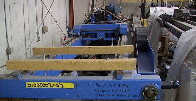
Huge Gantry Robot System ~ 20 by 40 foot working area? (There are about 43 images that follow so take a nice break or short nap while they load if this item is of interest to you.) The image above shows the top of the "bridge" for one unit from the end (the bridge moves left and right) with the apron or carriage in the background (it moved in and out of the image). The second bridge is black and is partially visible to the right. This system is much like a robotic bridge crane. The there are columns and beams that support rails overhead that the bridge can travel roughly 40 feet back and forth on. The carriage has about 20 feet of travel on the bridge. Images of the beams and columns are toward the end of all the images. (No, we don't have any images of this whole thing assembled or we would have shown at least one of them right away.) These robot systems were made by PAR systems. It is our present perception that these were originally multimillion dollar robot systems that never actually saw much use in a government laboratory. The image below shows the bridge and carriage of the black system. Above is a view of the black system bridge and carriage from the opposite side as above (ignore the tops of the old orange carts). The end-effector section of the blue unit can be seen lower left. A closer view of the carriage is shown below. The image above shows the endeffector area of the black system hanging below the carriage. The metal deck holds a bunch of equipment in the other system. (Note the Y and Z axis motion direction decals.) The image below shows the same area as the image above but from 90 degrees to the left. The image above shows the cable tray chain mechanism that allows for up and down movement of the endeffector. The image below shows a corner of the blue system bridge. The main gantry rail would run just behind the wood temporary mount at the lower right. Some of the bridge drive mechanism is just below the limit switch. The image above shows the blue system carriage drive motor upper middle-middle. The bridge drive servo motor is right middle. The image below shows the black system carriage and bridge drive servo motors. The image above is looking down through the blue system bridge at the endeffector area hanging under the carriage. The image below is the same as the one above except from the opposite side of the carriage. The image above shows the black system carriage and endeffector area from above and to the side. The image below shows the black system carriage from the side and above with the bridge drive servo motor in the lower left. Above is a top view of the blue system carriage. We think the extreme left of the image above is actually the end of the endeffector with a force sensor and mounting or coupling assembly. There is a large air cylinder shown in the image below. We don't know what its function is but it might be a balancer to offset the weight of the endeffector assembly. Our recollection is that the JR3 Model UFS-602 label is for a force sensor. This thing would obviously sit considerably further off the floor when mounted on the gantry rails. The image above is a close-up of the bridge drive. The image below shows a pallet of cables for the systems. The image above shows one of the control cabinets and the image below shows both of them. Forklift crinkled the back of the cabinet in the image above. PAR Systems labels on the cabinets. The control cabinets have integral air-conditioning units to keep them cool. The images that follow are of the Gantry Rail support columns and beams.  The corner support columns are tapered with broad 90 degree base to provide lateral bracing and are shown a the left of the image above. The interior support columns are shown in the middle and the horizontal beams the support the gantry rails are on the right. Some of the hoizontal beams, including those with gantry rail are shown in the images above and below. Some of the cable-way chain can also be seen. The image above looks to be of the interior support columns. The images above and below show the corner support columns. This is for an organization that has seriously large robotic needs. Other smaller robot systems may be listed separately or available on request. Condition looks hardly used, partially disassembled, dusty and weathered. We think we have all the major pieces but we have no idea what "minor" pieces might be missing. It seems obvious, but no, we have not tested it. It does look like it was basically functional when removed. Setup and debug assistance maybe available on a time and materials cost basis. Sold as-is. What you see is what you get (unless otherwise noted). We are in the Desert Southwest so items may need dusting/cleaning when they arrive.cavlon99 Click here to check for last minute updates and cavlon99 news. Items left beyond 20 days are subject to storage fees.  |